Building or buying?
That’s a question that often comes to the mind of amateur astronomers. This question is not always about money saving. Instead, if you consider getting a 10″ instrument or less, you’re very likely to spend more money building it than buying a commercial one. And I’m not talking about the countless hours spent making it.
However, most of the amateur telescope makers (ATMs) who decide to build their own instrument do it because they want to understand the optical phenomenon involved in a reflector. Another surprising advantage is that hand made optics (if guidelines are followed) tend to have a higher surface quality than the mirrors polished by industrial machines.
Building a reflector telescope can be decomposed in 2 steps: make the mirror and build the tube/mount. In this post, we’ll talk about the first one which is the most time consuming but also the most interesting.
Even though some builders prefer to buy commercial mirrors and fit them in a DIY structure, I believe that making a telescope mirror is probably the most rewarding part of the whole built. Starting from a rough glass blank, you can obtain an almost perfect parabola with surface errors in the range of 20 to 60 nm. And this, only by pushing a piece of glass by hand.
Let’s break down the process into 5 steps.
Rough grinding
This step is about making one side of the glass concave. It will give your mirror its overall focal ratio. If you make the centre deep, you will end up with a fast telescope (e.g. F/D = 4) well suited for deep sky observations. On the opposite, a shallow mirror (e.g. F/D = 8) will be performing very well on planets and the moon.
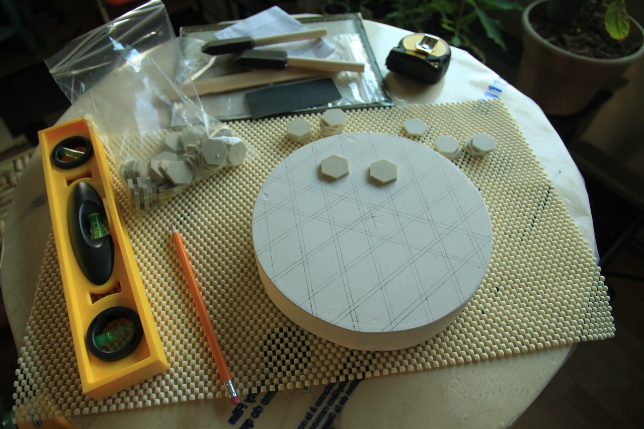
The theory behind grinding is that you can remove glass as long as you use a material with a higher hardness. Telescope makers use silicon carbide powders (a.k.a. carborundum) for this task. It is cheap and comes in various size (can range from #36 to #500). To be effective, the abrasive needs to be rubbed against the glass with a lot of pressure. That’s why we need a tool. It should be about the same size and weight as the glass. In the old days, ATMs were using another glass blank of lesser quality. Nowadays, this tool is most of the time made of ceramic tiles glued to a plaster or plywood disk.


Whether you buy or cast your own blank, it often turns up to have rough sides with marks left from the kiln. The first thing you want to do is to flatten one side (it will become the back) by grinding it against a flat piece of glass (e.g. a old window).
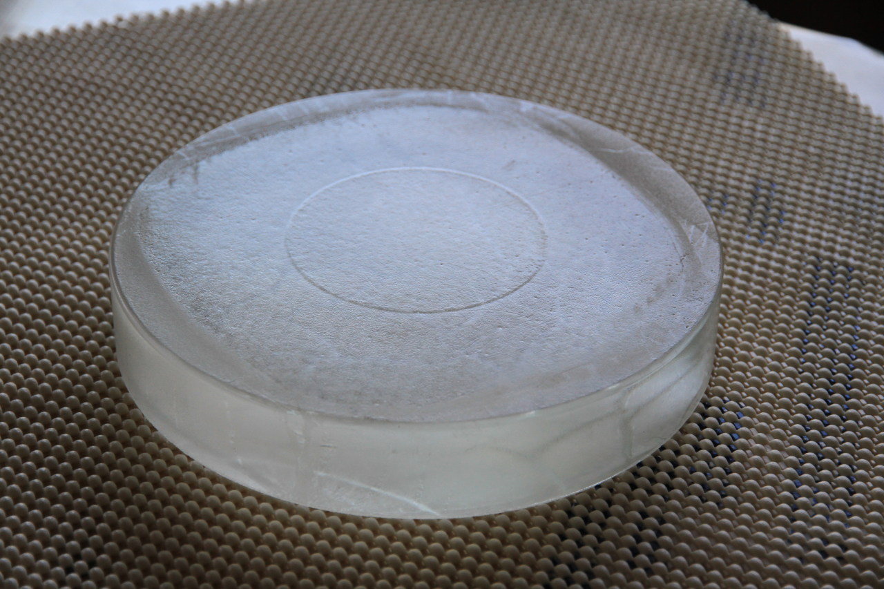


Once the back is flat, we can start to carve the front into its spherical shape. The theory here is that if you rub 2 circular blanks of approximately the same hardness with an abrasive in between, you will end up with a concave blank and a convex one. Our goal is to have the mirror concave and the tool convex. Gravity will help us here: more pressure will be applied on the centre of the overhanging blank and on the edges of the bottom one.


The courses to apply are pretty basic. They consist of long chordal strokes with mirror on top. After a few hours using coarse abrasive, you will end up with a face approximately spherical. If you were shooting for a high focal ratio telescope, you won’t have to grind for too long. On the other hand, for a fast scope, it can take you a lot more time.
Once the desired sagitta has been reached, it is time to make the surface more spherical (rough grinding usually creates a slightly conical surface). This is done by changing from chordal to normal stroke (1/3 centre over centre).

After a while, when the final shape has been reached, it is time for the second step: fine grinding.
Fine grinding
This step has only one purpose: removing the scratches and holes left by the rough grinding while keeping the shape of the surface.
To achieve that, we will work from coarser to finer abrasive. Moving from one grain size to the next should only be done once all the holes from the previous grain have disappeared. A common practice is to mark the bigger holes with a Sharpie and grind the surface until all of them are gone. Do the same thing for each grain size.

Once you reach the finer grains (at this point you might be using aluminium oxide instead of silicon carbide), the surface should start to shine a little when viewed from the side.
When the abrasive action becomes too small to be observable with the naked eye or with the help of a magnifier, you should consider moving to the third step: polishing.
Polishing
The goal here is to remove the rough surface left during fine grinding and obtain a smooth reflective surface.
During this step we’ll switch from mechanical grinding (silicon carbide and aluminium oxide) to chemical grinding (cerium oxide). The strokes stay the same but the difference happens at a microscopic scale. Instead of creating fractures in the glass, the cerium oxide will act like shears to remove peaks on the surface. Therefore, pressure no longer influences the speed of polishing.
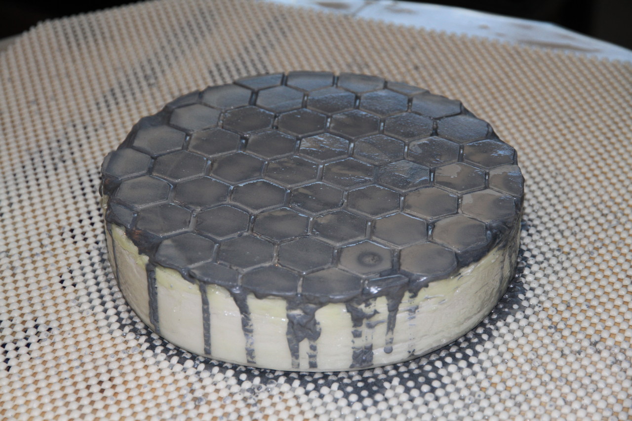
During polishing we are trading the ceramic tile tool for a softer material capable of holding the cerium onto its surface. The most commonly used material is pitch.

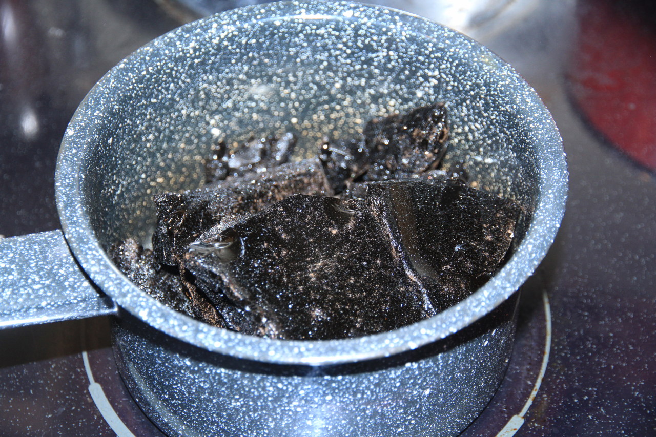
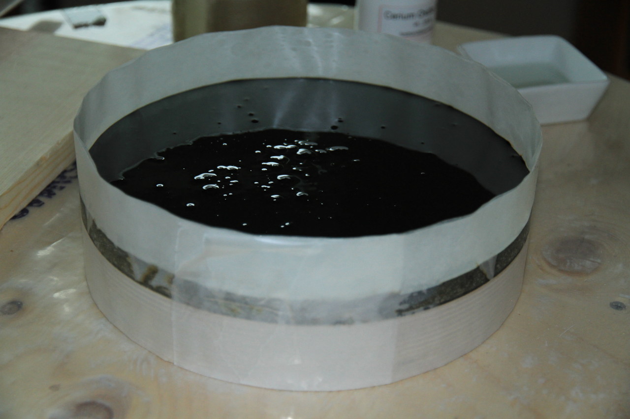
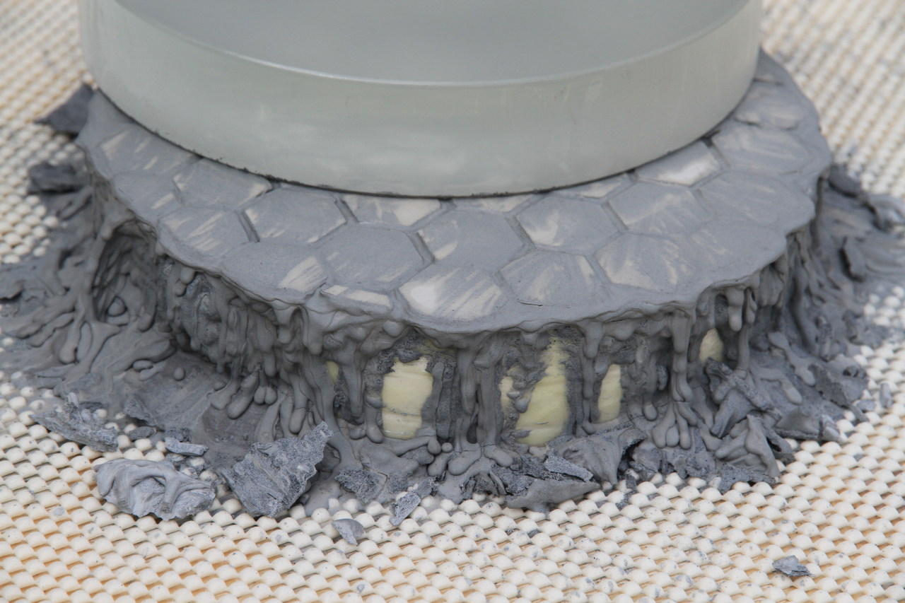
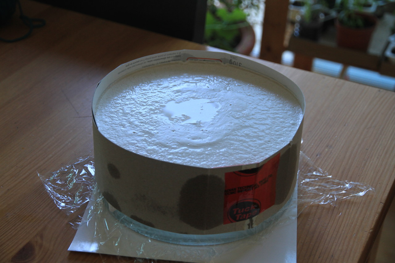
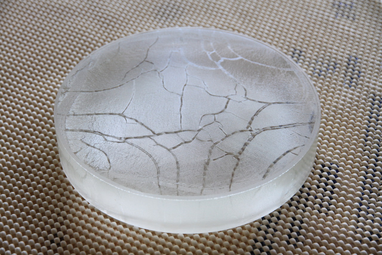
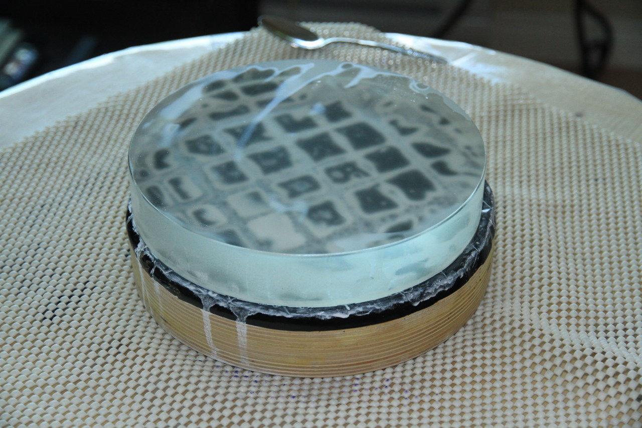
To create a pitch lap, we need to create a plaster or plywood disk the same side as our ceramic tile tool (very large mirrors can use smaller pitch laps), wrap the sides with tape and pour liquid lap on it. Once the lap starts to harden, it can be shaped into a convex form. By applying some cerium on the pitch, we can prevent it from sticking to the mirror when we finally press the glass against the pitch lap.


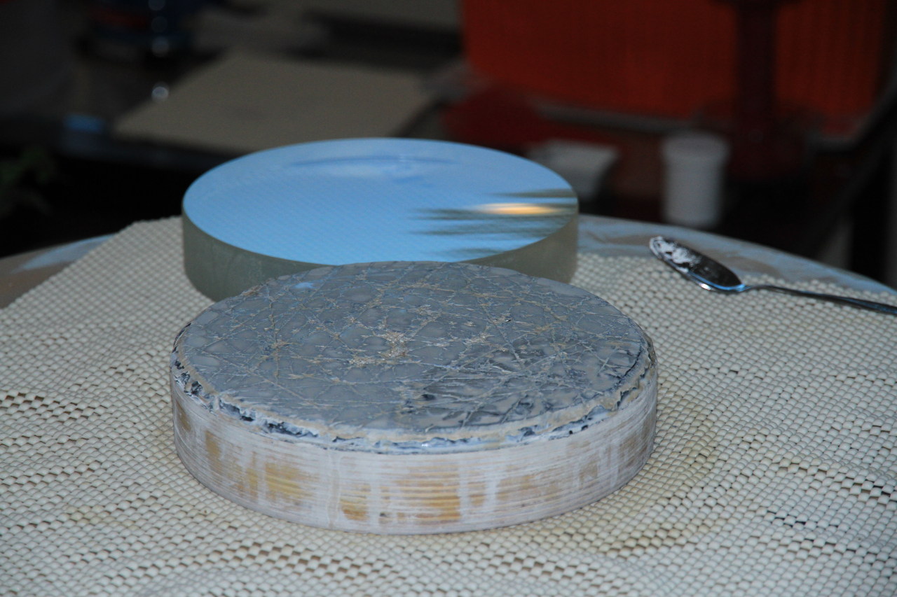
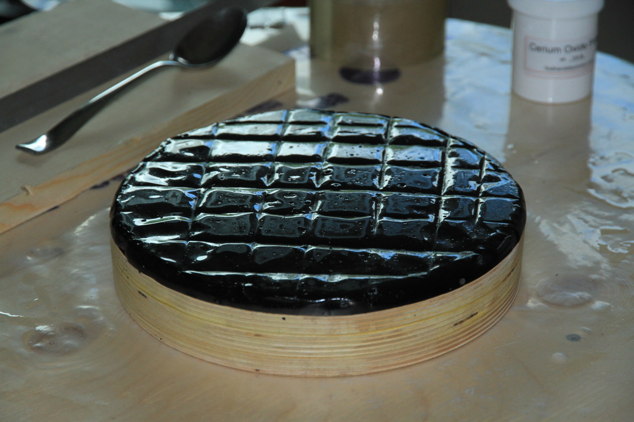
Once the pitch is hard enough, we need to cut grooves on the surface to increase the flow of cerium. An exacto knife under flowing water will do the trick just fine. It is worth mentioning that pitch is very hard to remove from almost all surfaces.
Now you can start polishing the mirror. It will start to get its reflective surface after a couple of hours but you will need a few hours more to make sure you remove all the rough surfaces from fine grinding.
Figuring
This task is probably the most time consuming. What we try to accomplish here is to change our perfectly spherical surface into a surface usable for astronomical purposes: The desired shape is a paraboloid.
A little bit of mathematics is required here: when parallel rays of light get reflected onto a spherical surface, they do not focus into a single point (blurry image). A paraboloid is the shape we are looking for. Basically, a paraboloid has a deeper centre and flatter edges than a spheroid.
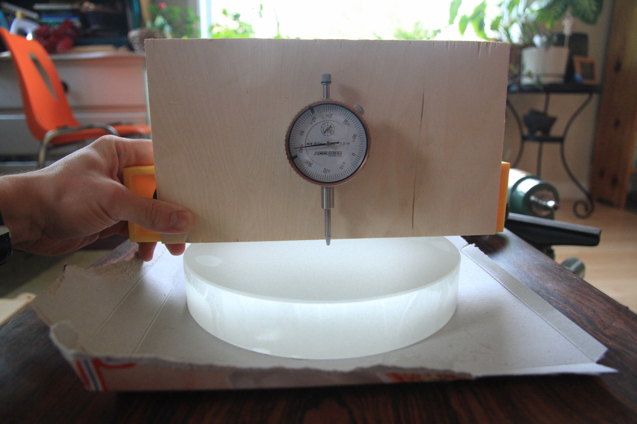
The difference between the spheroid and the paraboloid is very small and can’t be measured with the naked eye. We will need to build special tools to control the shape of the mirror.
To go from a spheroid to a paraboloid could take from a few hours to a few weeks depending on experience, focal ratio and luck.
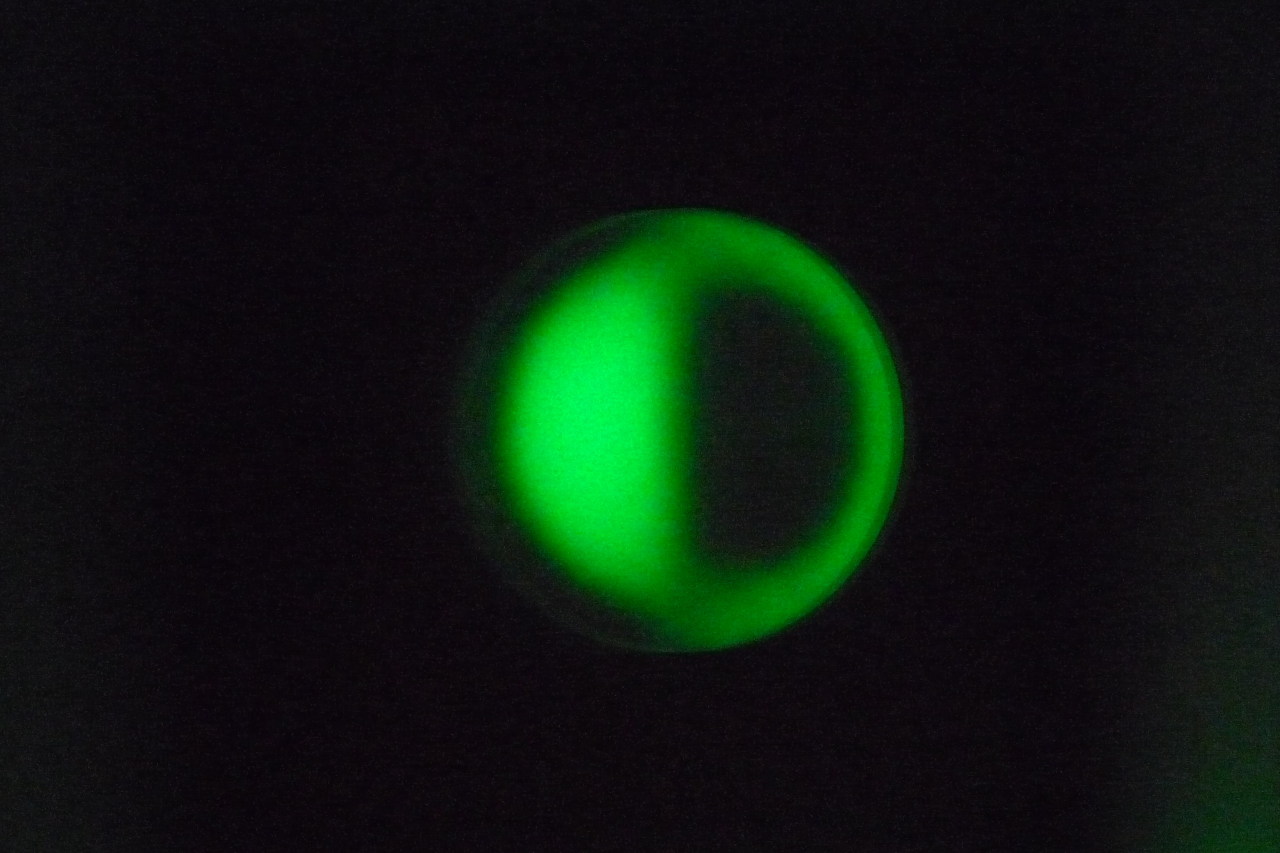
This is what a paraboloid looks like through a knife-edge test. The surface is lit from the right. We can see here that the centre is deeper and the edges flatter than a sphere.
The standard figuring stroke is the W shaped one. It deepens the centre and the edges. One of the common problem is overshooting the parabola. In that case, you end up with an hyperboloid and you will need to go back to the sphere before trying to parabolize again.
For low focal ratios, things get more complicated and you might need to use different strokes and alter the lap to achieve the paraboloid.
To control the shape of your mirror, you will have to use or build your own tools. A tool commonly used is the Foucault tester also known as knife-edge test. It is easy to build from materials available at the hardware store. A Ronchi screen is also a time saver tool. More complex tools such as interferometers give a more precise reading but are less affordable.


A mirror is considered finished when the differences between its surface and the ideal paraboloid are less than 1/8 of the wavelength of green light (510 nm). This means that the peak to valley distance should be less than 64 nm. While this is not the only test nor the most accurate, it is a good indicator of the overall quality of a mirror. The Strehl ratio is another value that can help to determine the entire optical quality of an instrument (a Strehl ratio can be calculated for the elliptical and the diagonal obstruction too).
Here is a ronchigram of a finished mirror. The right image is simulated from the Ronchi for Windows software. The web based Ronchi simulator by Mel Bartels is also very useful.


Here are common defects as seen through a Ronchi screen. The shape of the mirror can easily be deduced from the curvature of the lines.


To avoid doing the same mistake twice and learn from past errors, it is essential to keep a figuring log in a notebook. That way, you can associate a certain stroke with the desired correction.
Even though the Ronchigram gives a good indication of the mirror shape, it is still necessary to take measurements to quantify the surface precision. This can either be done by hand, in a spreadsheet or using dedicated software. A program like FigureXP does the job very well and provides you with a thorough surface error analysis. This is the profile of my finished mirror.

Surface coating
This is the step where your mirror receives its reflective surface. After aluminization, a mirror goes from 5% to more than 90 – 95% reflectivity depending on the type of treatment applied. A protective SiO2 layer is often applied on the aluminium to preserve it from oxidization.
Even though it is possible to build your own vacuum chamber and coat your own mirrors, it is usually not worth it unless you have tens of large mirrors to aluminize.
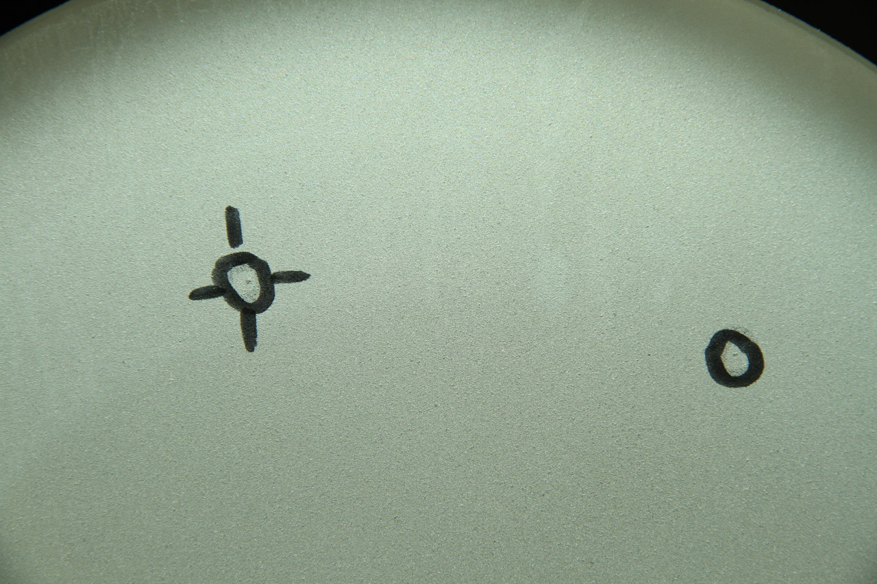
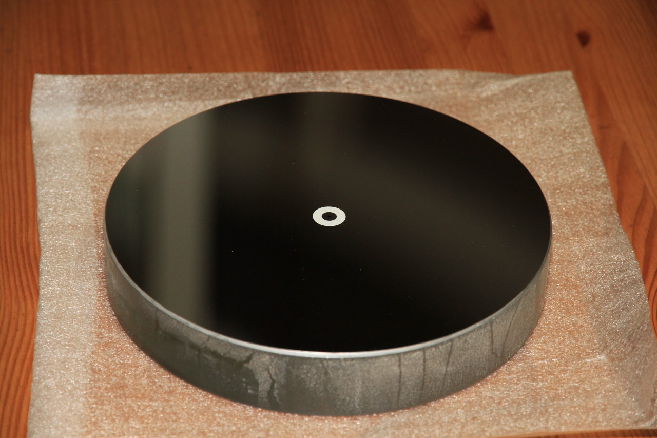
Here is a picture of my finished mirror with a true centre marking.
References
La construction du telescope amateur, Jean Texereau. An ATM reference
Stellafane.org, thorough documentation for telescope makers
bbastrodesign.com, Mel Bartels. Modern approaches to mirror making and telescope designs
Phillip Loss
In 1989, my then 13 year old daughter ground a 6″ F6 mirror that tested to better than 1/20 wave in white light. Back then you could not get a pure green light source at any reasonable price. She did this in a class that myself and a friend of mine taught for 2 years. It was a real delight to see her pride in the project. She used the scope to this day. Because of the accuracy of the parabola, the contrast on this scope is outstanding. My 7yr old granddaughter absolutely loves looking through it as well. Thanks for the article. PJ Loss
Nikos
I need to have a small piece of glass curved to a spherical curvature with radius of 2200mm (focal length of 1100mm). Can you make custom mirrors?
B. Teddy
Hello,
Why are the grinding tools always square or hexagon tiles? Can they be round, diamond, oval etc…
What is the depth of the concave per diameter.
Thomas
The tiles can have any shape but it is important to leave some room between the tiles for the abrasive to flow freely on the surface of the mirror.
If you use circles or ovals, you will end up with large gaps between the tiles in some places. That would reduce the efficiency of your polishing tool and it would take longer to grind your mirror.
A geometrically repeating pattern is therefore the preferred solution because they leave less gaps.
Another thing to consider is the symmetry of the tile. This is less important because you are supposed to rotate your grinding tool while you’re moving it but consider a tool with squares and a tool with rectangles. Depending which orientation you are using it, the tool with rectangles will not have the same efficiency when rotated at 90 degrees. In one direction, it will offer a lot of grinding power but push out the grit off the mirror, in the other direction, it will offer less friction.
A tool with hexagons is probably the best option since it offers the same efficiency in 3 directions as opposed to squares who only have 2 degrees of symmetry.
The depth of the mirror depends on the diameter of the glass and the focal ratio you are trying to achieve. A fast mirror (low F/D ratio) will be more concave and will take longer to grind and polish.
Marcus Motta
Dear Mr. Thomas Jacquin
My name is Marcus Motta and I´m writing this e-mail from Brazil
First all congratulation for your excellent work on your site,…. Very organized.
I would like one information. I live in Brazil and here it’s very difficult to find glass with thickness bigger than 19 mm ( ¾ inch).
In your opinion what is the biggest diameter that a have to attempt to make a Newtonian telescope mirror? Is possible to stick (to glue) two glasses to increase the thickness?
What is the ratio between the diameter & the thickness of the Mirror?
It is possible to make a 12 inch (300 mm) mirror with ¾ inch, 19 mm ??
If not…It is possible to make a 10 inch (250 mm) mirror with ¾ inch, 19 mm ??
Witch kind of glue did you used in your sandwich mirror …ultraviolet glue for glass…its works well ?
With book do you recommends to follow? I purchase 5 of them….
– Standard Handbook for Telescope Making – Neale E. Howard
– Build Your Own Telescope – Richard Berry
– How to Make Telescope – Jean Texereau
– Advance Telescope Making Techniques_V1 & 2 – Allan.Mackintoch
– Amateur Telescope Making – Stephen F. Tonkin
Thanks a lot for any information.
Best regards, abraços
Motta, Motta
+55 51 9.9659.1961
+55 21 9.9986.4155 – WhatsApp
mdbmotta@gmail.com
mdbmotta@hotmail.com
skype: marcus_motta
Thomas
Hi Marcus,
The problem with thin mirrors is that they flex more easily during grinding and polishing, making it hard to achieve the required surface precision. They also need a more complex mirror cell (additional support points). Plop is a useful software to let you calculate the number of points needed based on the diameter and thickness of the glass:
http://www.davidlewistoronto.com/plop/design.htm
http://www.davidlewistoronto.com/plop/
The usual full thickness ratio is 1:6 which means normal polishing techniques can be used on this kind of mirror. Mirrors larger than 1/6 their thickness are considered thin mirrors and will need more thoughts put into it (back of the mirror must be even and padded during polishing, used an appropriate mirror cell design, etc).
That being said, it is possible to experiment with various configurations. I have successfully made a 10″ mirror with 1″ thickness (1:10 ratio) and it performs very well. It is also supported by 9 floating points.
Some people have used thin layers of glass fused together in a kiln. Mike Davis is one of them and it seems to work quite well:
http://www.mdpub.com/scopeworks/fused_blanks/
Another thing I have seen recently is people slumping glass onto a mold in a kiln. It seems to work just fine as long as you have the equipment to do it and you take the appropriate measures to support the mirror during the polishing/figuring. Mel Bartels has a nice page about that:
http://www.bbastrodesigns.com/slump/MoldMaking.html
I believe you should be able to glue glass together as long as they have the same properties and no obvious strain although I never attempted it. Make sure to polish the back to make it flat.
I have followed Jean Texereau’s book (old but a great reference guide) for my first telescope and I’ve heard good things about the Richard Berry one.
Please let me know if you successfully glue glass together.
Thomas
Martin Andrews
Hi, this link http://www.mdpub.com/scopeworks/fused_blanks/ is to a web page done by Mike Davis not David Davis. I don’t think David Davis has a web page.
Thomas
Thanks Martin, I’ll fix it right now 🙂
Heather Hodge
Wow..just wow!! I wish I understood your explanation of this. I don’t understand what the circle piece is for? It looks too big to be able to use as a sort of “grinder/polisher, but maybe I was misinterpreting the size of it. It looks like to me that it’s almost the same diameter as the glass, which seems like to me would be too large to create the right shape!? What am I missing here?
Honestly idk why I took the time to read this entire article because I’m sure I couldn’t afford to buy all the materials needed to make my own mirrors anyway😞, but im still really curious to understand your instructions.
I do have one more question though..so if I want to build a reflector scope with the intent of viewing DSOs, would I need a smaller focal ratio or larger? When I say smaller or larger I mean like f/2 = smaller f/8= larger. Which one is the deeper of the two? And by deeper, I’m imagining it as requiring more grinding, which in turn would actually mean the middle of the glass would be thinner. I hope that makes sense!
Oh and one more thing!!..so if I were to make a scope with specs for deep sky viewing, would that mean that it wouldn’t work well for viewing planets, or would that still be possible, just more difficult to locate objects due to a smaller field of view? For instance, would it be possible to see Saturn & Jupiter with a scope for deep sky viewing?
Thomas
Hi Heather,
The grinding and polishing tools are the same size as the piece of glass. When you rub the glass over the edge of the tool, it grinds the center of the glass, hence making it concave. Over time, the peaks and valleys get all shaved by the polishing process and you end up with the right shape.
To view DSOs, you need to accumulate a lot of light which means you need a large diameter. For the same F/D ratio, a 10″ mirror will give 50% more light than an 8″ one.
Think of it as a bucket accumulating light just like a bucket accumulates water when it rains. The larger, the more water you get.
Regarding the focal ratio, a f/2 mirror will produce bright wide angle images which is well suited for nebulae and large galaxies like M31 and M33. An f/8 mirror will produce darker images but higher magnification and high contrast well suited for planets, planetary nebulae and bright galaxies from the Messier catalog.
You can still use an f/2 telescope to view planets and small objects by using a small focal eyepiece and barlow lenses.
The main thing is that building a mirror with a small F/D ratio can be extremely hard. I only know a few people who have successfully produced mirror under F/D=3.
A great first telescope project would be a 6 or 8″ with a F/D=8 ratio because it is easier to build and use.
michel
i have a spherical mirror and i remouve the alluminium…
I would like to parabolise this mirror…
it is a 8 in. 3.4f do i need other grit than cerium oxide and the pitch tool. to modify the curve…?
I dont have any grit… just the polishig cerium oxide…!
Is it possible?
Thank’s
Thomas
Hi Michel,
If your mirror is already spherical and polished, you will be able to parabolize it using cerium oxide.
A f/3.4 mirror will require a bit more effort than a classic f/8 or f/6 but it’s doable. I know some people have parabolized f/2.6 mirror manually.
michel
Thank’s for fast replay! I am verry happy to your comments..
I will do it , this summer…ThanK’s again,….I will give your the results..asap…
Tony
Thomas,
I am new to this and I have a question which may seem naive to those experienced in the art. I get the idea that the glass is there to support a thin layer of aluminium which is the reflective surface. In which case why is glass the favoured material? Is there any good reason why it should not be made in say aluminium, or filled epoxy? The same grinding and polishing methods could be applied but the blank could be made closer to the required shape in a manual lathe or preferably a CNC lathe or 3 axis CNC milling machine.
Thomas
Hi Tony,
This has something to do with the stability of the material in response to thermal variations. Look at the coefficient of thermal expansion for various materials https://www.sciencedirect.com/topics/engineering/linear-coefficient-of-expansion
In the past, mirrors were built using metal. Lord Rosse’s 6ft mirror was made of copper and tin. However these were quickly abandoned in favour of glass.
Nowadays, borosilicate glass is a fairly common material with a very low thermal expansion. It is also relatively cheap in comparison to certain metals which makes it a good choice for telescope mirrors.
Hope that helps,
Cheers
Tony
Thanks for that. I thought that Aluminium and glass had similar expansion coefficients of expansion but when I checked your reference I see that I grossly over estimated the coeff of glass.
After sending my original question I realised why you need to start with a near flat surface rather than pre-shape it. For the grinding you need the two surfaces to match one another more or less from beginning to end. You would need to have both surfaces pre-shaped if you went that route to save time.
Thomas
Technically, you could do the grinding of the glass with a CNC mill and a diamond tool but it is not tool practical for amateurs. Also, if not done with proper lubrication, you could end up with glass dust in the air.
Another way of creating mirrors is by slumping a piece of glass over a convex plaster mold. It has the benefit of being faster if you make a low F/D ratio telescope. However, you need a large kiln for that as well as a proper support for the mirror during polishing.
Tony
Yes I thought of all of those methods but you would still have to use a pre-formed grinding mate for grinding the rough shape. I guess that is possible.
Ovidiu
I don’t understand too much of this. The basic idea is easy to understand though.